Design the VLSM Address Scheme Part 3. Cable and Configure the IPv4 Network Background Scenario.
8 2 1 4 9 2 1 5 Packet Tracer Designing And Implementing A Vlsm Addressing Scheme Instructions Answers
8214 Packet Tracer Designing and Implementing a VLSM Addressing Scheme Packet Tracer Designing and Implementing a VLSM Addressing Scheme Answer Version Answer Note.

. 8214 Packet Tracer - Designing and Implementing a VLSM Addressing Scheme Packet Tracer - Designing and Implementing a VLSM Addressing Scheme Answer Version Answer Note. Packet Tracer - Designing and Implementing a VLSM Addressing Scheme. Optional activities are designed to enhance understanding andor to provide.
You will subnet the network address. Use the third subnet to accommodate the third largest LAN. The network has the following requirements.
Red font color or gray highlights indicate text that appears in the Answer copy only. Design the VLSM Addressing Scheme Step 1. 8314 Packet Tracer Implementing a Subnetted IPv6 Addressing Scheme Packet Tracer Implementing a Subnetted IPv6 Addressing Scheme Answer Version Optional Packet Tracer Answer Note.
Vlsm addressing schemes cisco press. Ccnav2 chapter 6 skills assessment pt w answers. Design the VLSM Addressing Schstronge Step 1.
Red font color or Gray highlights indicate text that appears in the Answer copy only. 8214 Packet Tracer - Designing and Implementing a VLSM Addressing Scheme Netacad. Topology Objectives Part 1.
Red font color or gray highlights indicate text that appears in the Answer copy only. The largest LAN is ASW-4 with 58 hosts. Examine the Network Requirements Part 2.
Examine the Network Requirements Step 1. Divide the DisplayNet network based on the number of hosts per subnet. Assign IP Addresses to Devices and Verify Connectivity.
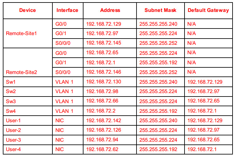
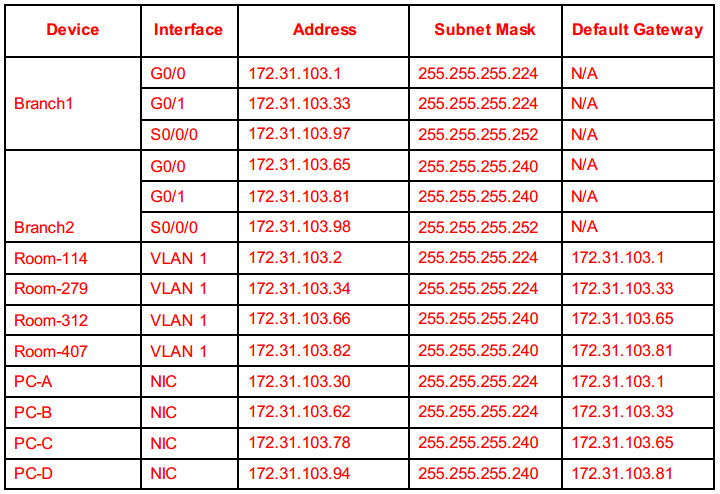
Addressing Table Device Interface. In this activity you are given a 24 network address to use to design a VLSM. Addressing scheme answer bing.
Examine Network Requirements Part 2. Design the VLSM Addressing Scheme Part 3. You will subnet the network address 101148024.
2015 Cisco andor its affiliates. Design the VLSM Addressing Scheme Part 3. Packet Tracer Designing and Implementing a VLSM Addressing Scheme Addressing Table.
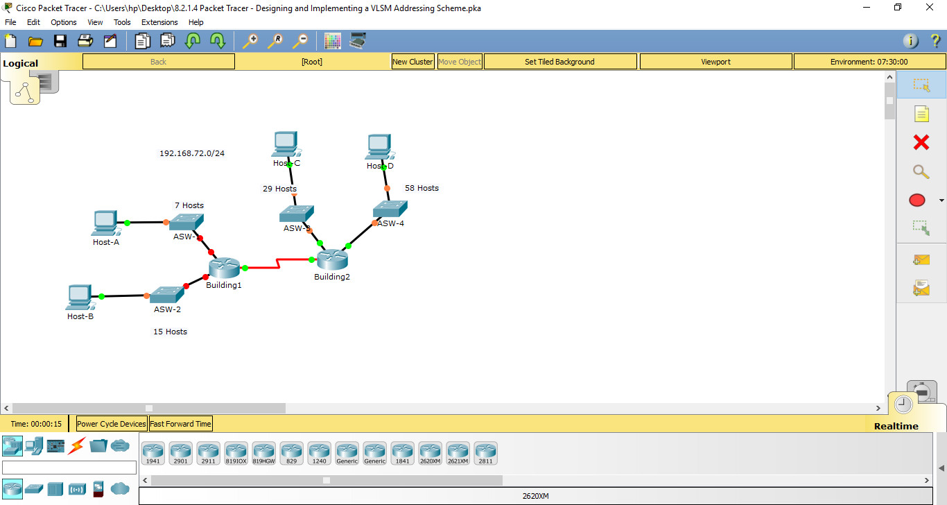
Based on a set of requirements you will assign subnets and addressing configure devices and verify connectivity. Topology You will receive one of three possible topologies. 9 2 1 4 lab designing and implementing a vlsm addressing.
Red font color or gray highlights indicate text that appears in the Answer copy only. Use the second subnet to accommodate the second largest LAN. Lab Designing and Implementing a VLSM Addressing Scheme Instructor Version Instructor Note.
Lab Designing and Implementing a VLSM Addressing Scheme January 27th 2016 - Lab Designing and Implementing a VLSM Addressing Scheme Topology Objectives Part 1 Examine Network Requirements Part 2 Design the VLSM Address Scheme Answers Calculating A Vlsm Addressing Scheme taxihb de. View 8214 Packet Tracer - Designing and Implementing a VLSM Addressing Schemedocx from CCNA 1301 at Texas State Technical College Waco. Divide the 19216872024 network based on the number of hosts per subnet.
8214 Packet Tracer Designing and Implementing a VLSM Addressing Scheme Packet Tracer Designing and Implementing a VLSM Addressing Scheme Answer Version Answer Note. Vlsm addressing schemes cisco press. This video shows the packet tracer activity Designing and implementing a VLSM addressing scheme.
Determine the number of subnets needed. Oct 25 2016 8214 Packet Tracer - Designing and Implementing a VLSM Addressing Scheme Instructions Answerspka file free download Completed 100 2016 2017 VIEW ANSWER Find Similar 8214 Packet Tracer - Designing and Implementing a VLSM. Assign IP Addresses to Devices and Verify Connectivity.
In this activity you are given a 24 network address to use to design a VLSM. 8 2 1 4 packet tracer designing and implementing a vlsm. 8214 Packet Tracer Designing and Implementing a VLSM Addressing Scheme Packet Tracer Designing and Implementing a VLSM Addressing Scheme Answer Version Answer Note.
This will give us 4 subnets 22 4 with 64 hosts per. View 9215 Packet Tracer - Designing and Implementing a VLSM Addressing Scheme from NETI 105 at Ivy Tech Community College of. Determine the number of subnets needed.
Examine the Network Requirements Part 2. Packet tracer 3 lab vlsm 2 iws collin edu. Packet Tracer Designing and Implementing a VLSM Addressing Scheme Addressing Table.
8214 Packet Tracer - Designing and Implementing a VLSM Addressing Scheme Instructions Answersapk file free download Completed 100 2016 2017. This video shows the packet tracer activity Designing and implementing a VLSM addressing scheme. Design the VLSM Addressing Scheme Part 3.
8214 Packet Tracer Designing and Implementing a VLSM Addressing Scheme Packet Tracer Designing and Implementing a VLSM Addressing Scheme Answer Version Answer Note. In this activity you are given a 24 network address to use to design a VLSM addressing scheme. Examine the Network Requirements Part 2.
Assign IP Addresses to Devices and Verify Connectivity. Examine the Network Requirements Step 1. Packet Tracer Designing and Implementing a VLSM Addressing Scheme Addressing Table Objectives Part 1.
The norton saga bikerglory. Topology You will receive one of three possible topologies. Red font color or gray highlights indicate text that appears in the Answer copy only.
11938214 Designing and Implementing a VLSM Addressing Scheme Instructions Answers. Use the first subnet to accommodate the largest LAN. Red font color or Gray highlights indicate text that appears in the instructor copy only.
Packet Tracer - Designing and Implementing a VLSM. Red font color or gray highlights indicate text that appears in the Answer copy only. 8214 Packet Tracer - Designing and Implementing a VLSM Addressing Schemepdf.
DOWNLOAD 9215 Packet Tracer - Designing And Implementing A Vlsm Addressing Scheme Answers DOWNLOAD 9215 Packet Tracer - Designing And Implementing A Vlsm Addressing Scheme Answers. Use the first subnet to accommodate the largest LAN. Topology You will receive one of three possible topologies.
Subnet 19216872024 into 19216872026. Topology You will receive one of three possible topologies. 11938214 Designing and Implementing a VLSM Addressing Scheme Instructions Answers Based on a set of requirements you will assign subnets and addressing configure devices and verify connectivity.
8 2 1 4 9 2 1 5 Packet Tracer Designing And Implementing A Vlsm Addressing Scheme Instructions Answers

11 9 3 8 2 1 4 Designing And Implementing A Vlsm Addressing Scheme

8 2 1 4 Packet Tracer Designing And Implementing A Vlsm Addressing Scheme Youtube
8 2 1 4 Packet Tracer Designing And Implementing A Vlsm Addressing Scheme Docx Packet Tracer Designing And Implementing A Vlsm Course Hero

Ccnav6 S1 8 2 1 4 Packet Tracer Designing And Implementing A Vlsm Addressing Scheme

8 2 1 4 Packet Tracer Designing And Implementing A Vlsm Addressing Scheme Youtube
11 9 3 8 2 1 4 Designing And Implementing A Vlsm Addressing Scheme

8 2 1 5 9 2 1 4 Lab Designing And Implementing A Vlsm Addressing Scheme Youtube
0 comments
Post a Comment